We analyzed a simplified cable-supported bridge three ways: hand calculations, finite element analysis and a physical load test. A flat deck hangs from four corner towers on 45° cables, kept simple so load paths are easy to trace. We solved for allowable load at a safety factor of 2, deck deflection, cable tension and tower bending. I was the team's manufacturer.
← All projects
Suspension Bridge
Hand calculations, FEA and a loaded prototype all pointed to the same weak spot: the deck at midspan.
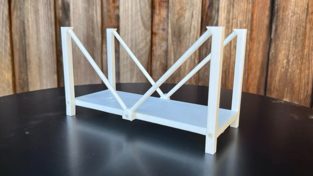
Overview
Challenge
The project started from the 2018 pedestrian bridge collapse at Florida International University and how analysis tools can help find failure points. The hard part was making a small printed model match the math: printed PLA is not solid, so a textbook modulus overstates stiffness, and printed joints are never perfectly fixed.
“Material calibration is just as critical as geometry and boundary conditions when building a reliable FEA model.”
Process
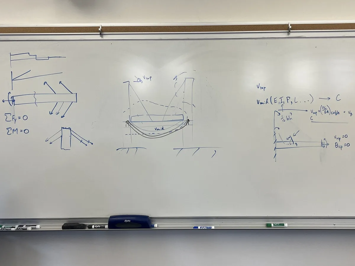
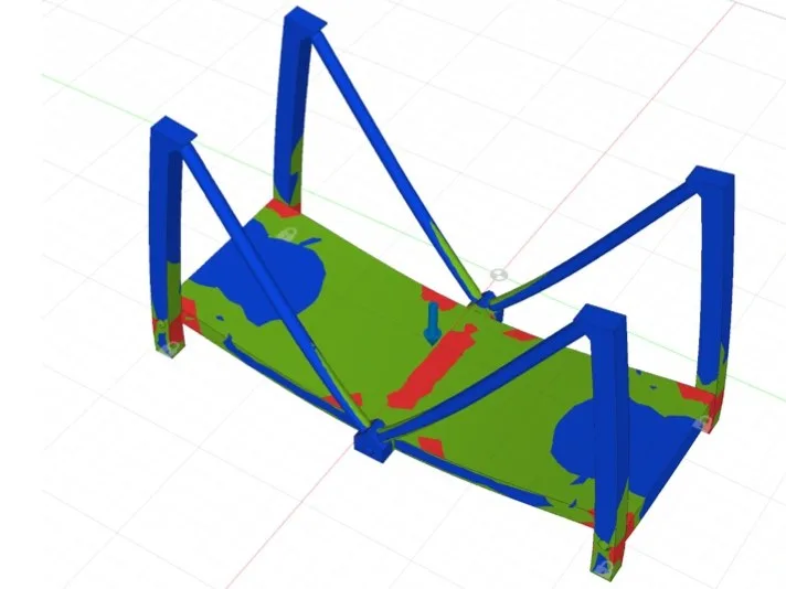
Our first concept was more complex; peer review pushed us to simplify it so deck bending was easy to isolate. I argued for a single-piece print to avoid unreliable joints. When an early print proved too thin, I revised the CAD and reran the FEA. We also printed at several infills; 5% best matched the model.
Hand calculations
Beam theory and statics for deck bending, deflection, cable tension and tower bending at SF = 2.
Simulation
Linear static FEA with a distributed deck load, fixed corners and gravity for self-weight.
Print and test
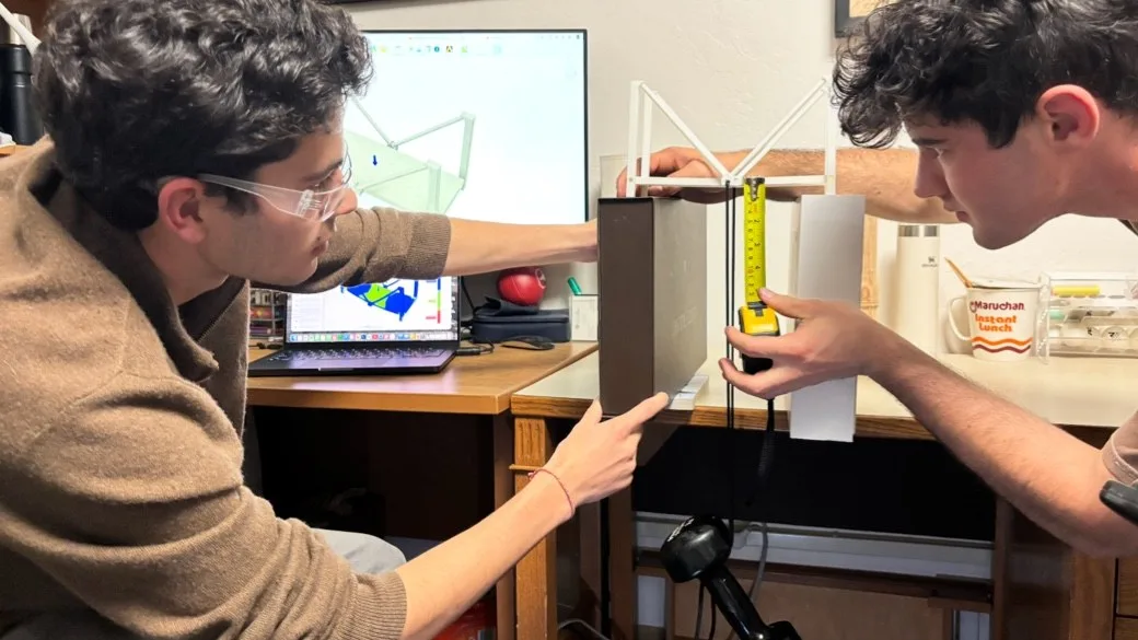
One PLA part at 5% infill, loaded at midspan in steps while we measured deflection.
Outcome
All three methods agreed that deck bending at midspan governs failure; tower bases came second and the cables never governed. The analysis put allowable load at 456 N, first yield at 911 N and failure at 1823 N. The prototype deflected about 4 mm against 11.2 mm predicted by hand: solid printed shells made the deck act like a sandwich panel, and real joints added restraint.
456 N
Allowable deck load at a safety factor of 2
911 N
Predicted load at first yield
~4 mm
Measured midspan deflection under load
SpinGrip